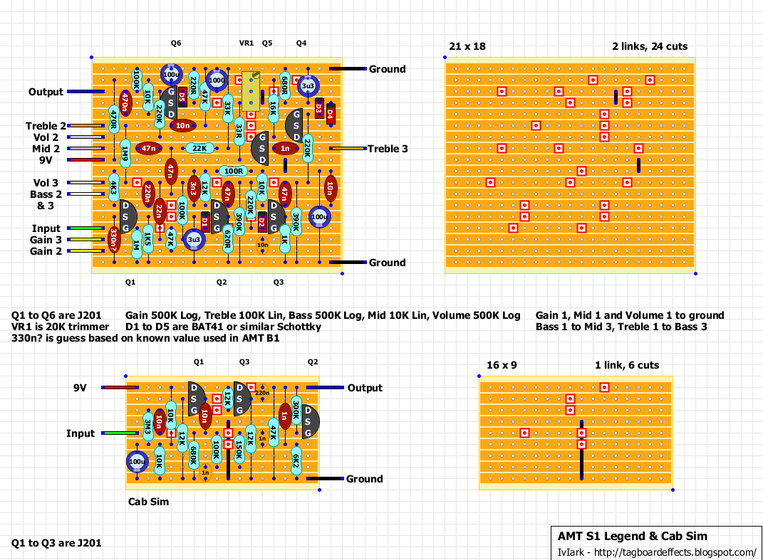
Verified but with a caveat. Two people have verified the main board and the cab sim separately, but there are definitely biasing issues dependant on the JFETs you use. This was designed around the 2SK208 SMD transistors and so when using the common through-hole JFET, they will need biasing differently and so it would be a good idea to swap the source or drain resistors for trimmers for all JFETs other than Q4 which already has a trimmer. It may be a good idea to socket those resistor connection points so you can use a single trimmer to work out the required resistance to get the correct drain voltage for each transistor, and then using an appropriate value resistor in the socket rather than having trimmers all over the place.
Thanks to Ice-9 on FSB for tracing and supplying the schematic. The original of this pedal used 2SK208 transistors which are only available in surface mount form. I have opted for J201’s in the layout, but a bit of experimentation may be the order of the day in terms of trying other JFETs, and associated components to get them to bias. So this may be one for the tweakers at this stage until we have some good results with the alternative JFETs.
Note that the input to the cab sim, would come from the output of the main board, so you would either have two output sockets (with and without cab sim) or you could have a single output socket and use a toggle to true bypss the cab sim.
From the manufacturer:
