This isn’t a complete reference of every Tone Bender MKIII / MKIV ever made. It’s a working table compiled from multiple online sources and gut shots, so treat it as a guide rather than absolute gospel.
In some cases, it’s difficult to have a definitive set of values for any one pedal, as they are known to change over time, with different production runs.
Where values are unknown or unsure, you’ll see a question mark in the table.
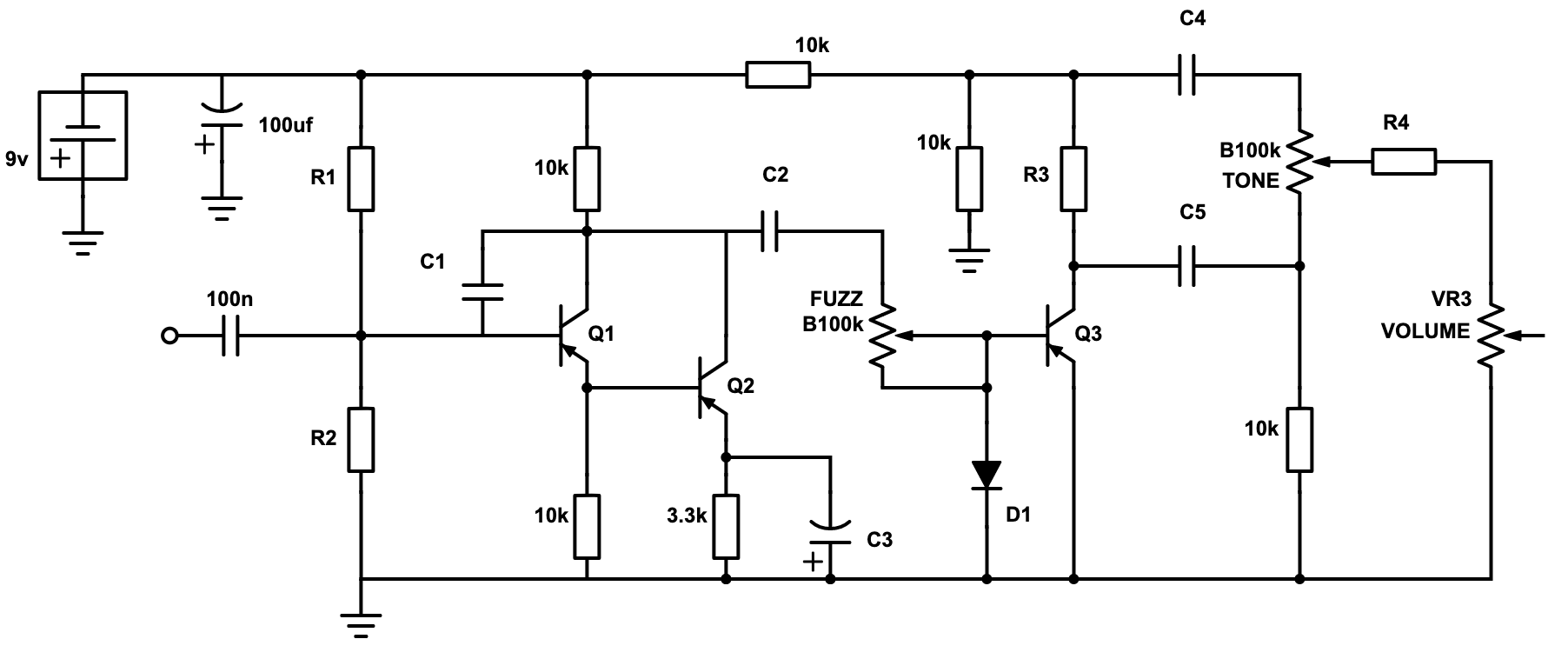
GENERIC MKIII / MKIV TONE BENDER SCHEMATIC
Common components have been left as is, and I know the 100uf cap varies, but it makes no difference really so I didn’t see the point of listing every variation. Arguably, there’s also no difference between a 220pf and a 200pf cap either, but I put that in any way.

- Bias resistors R1 & R2 on the base of Q1. These are conveniently marked with asterisks below – they frequently vary.
- The capacitor C3 on the emitter of Q3. This effects the bass response.
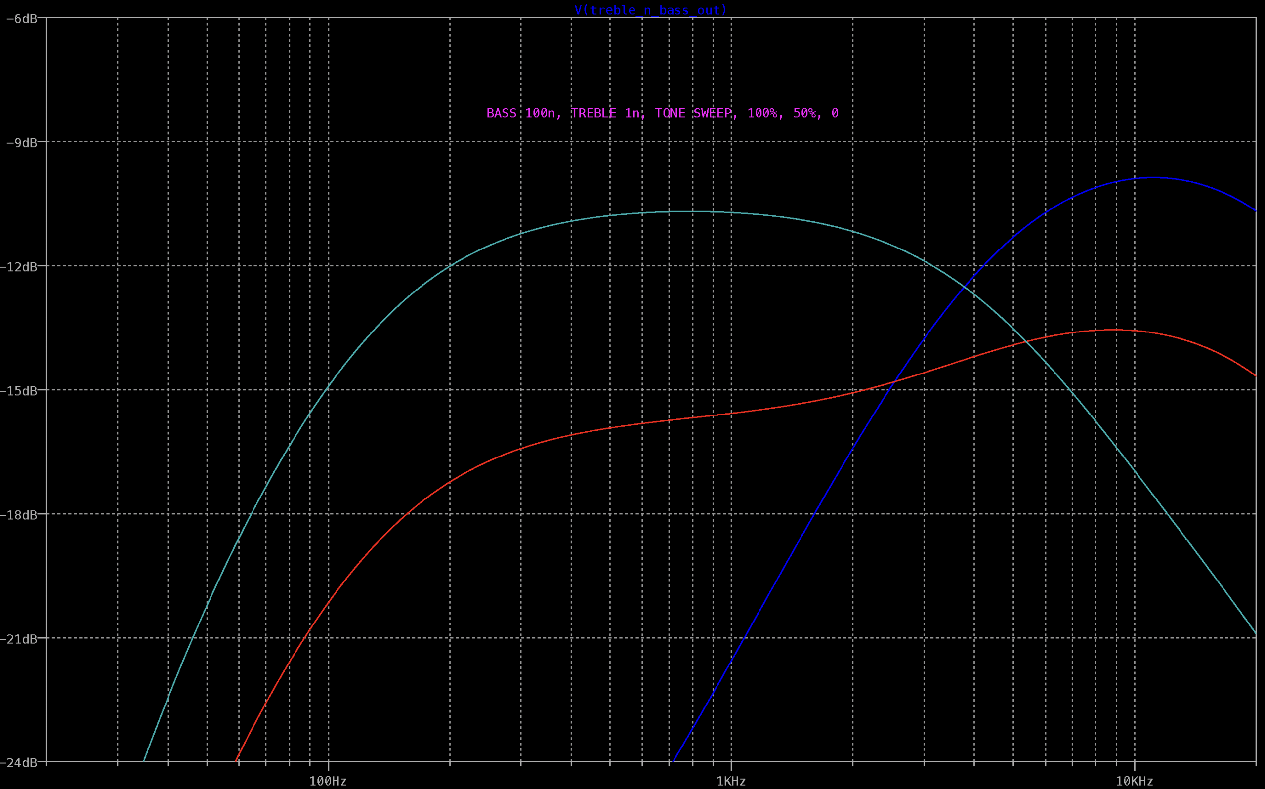
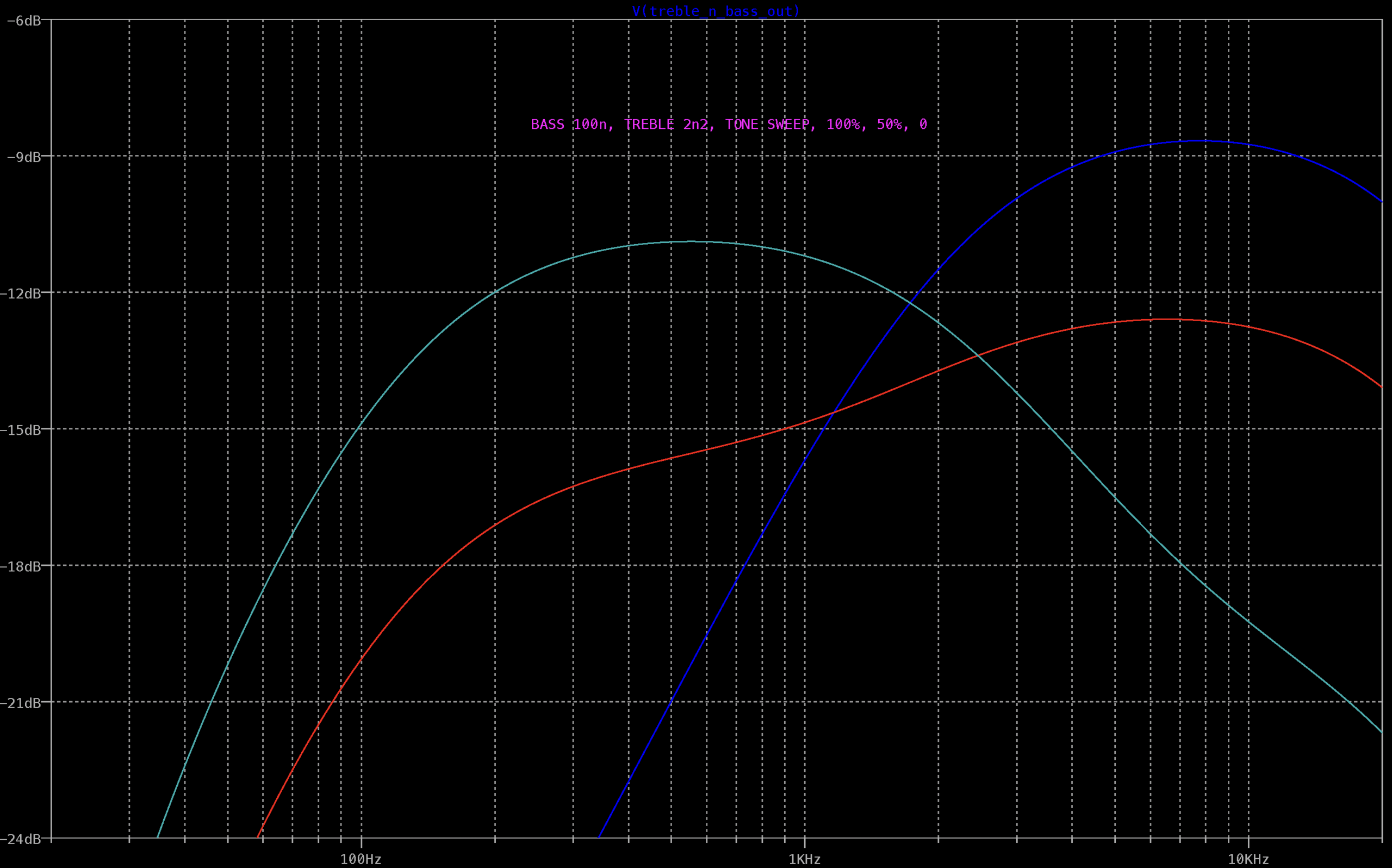
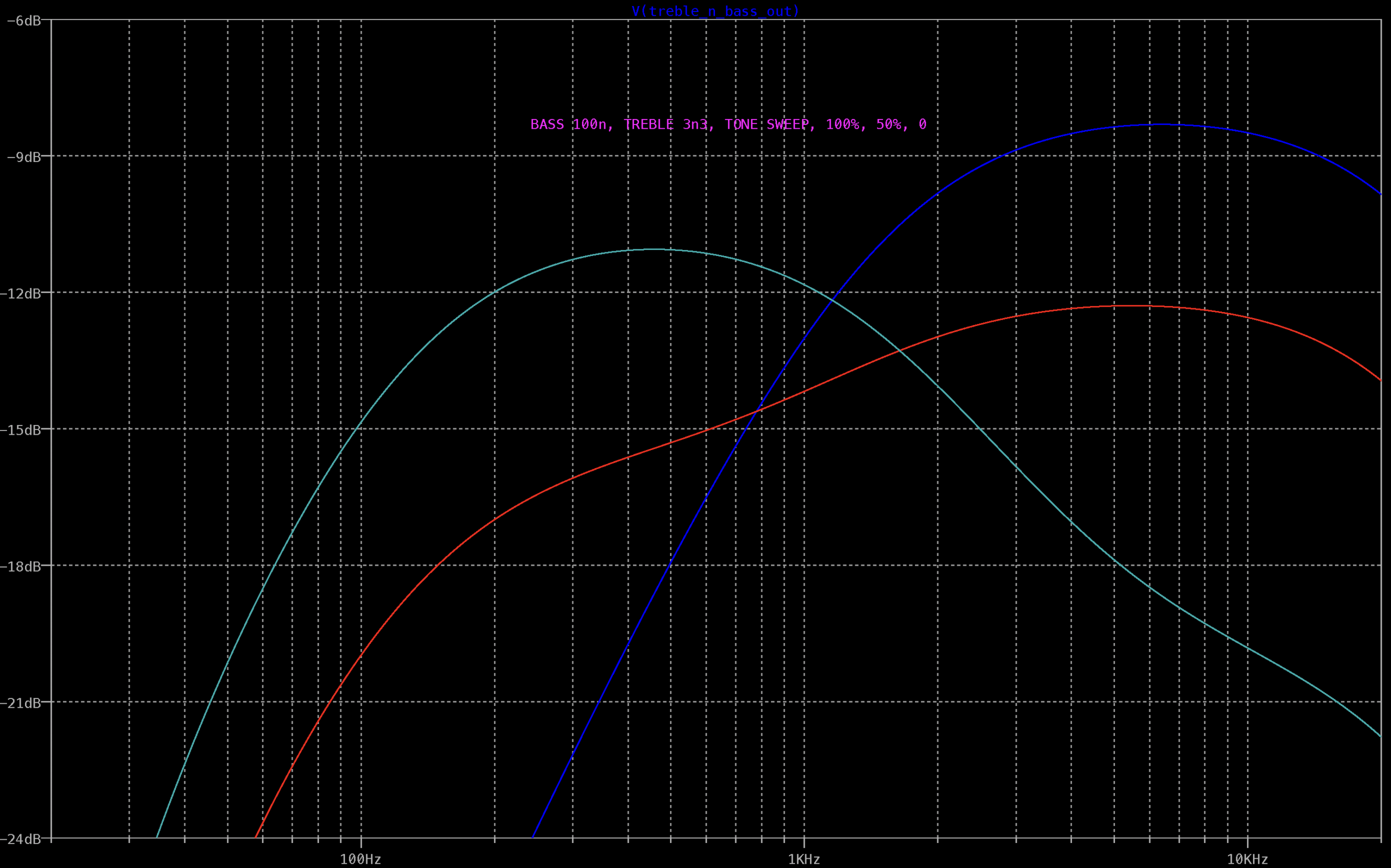
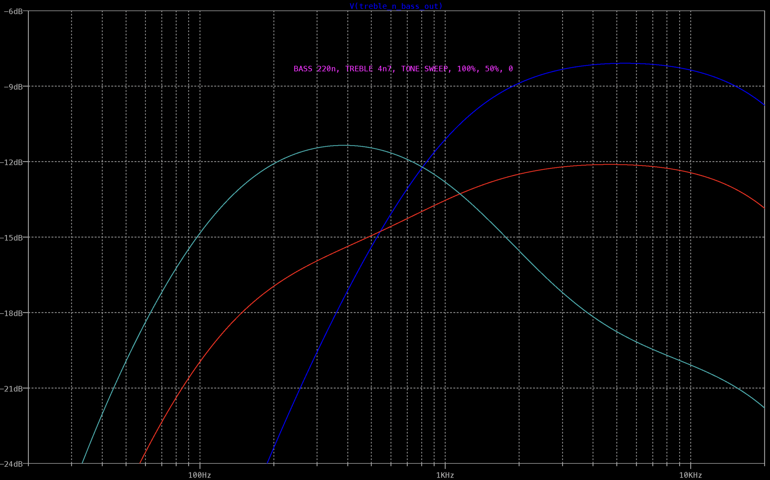
- The treble and bass caps – these are nearly always tweaked on D*A*M builds (which I quite like and frequently use)
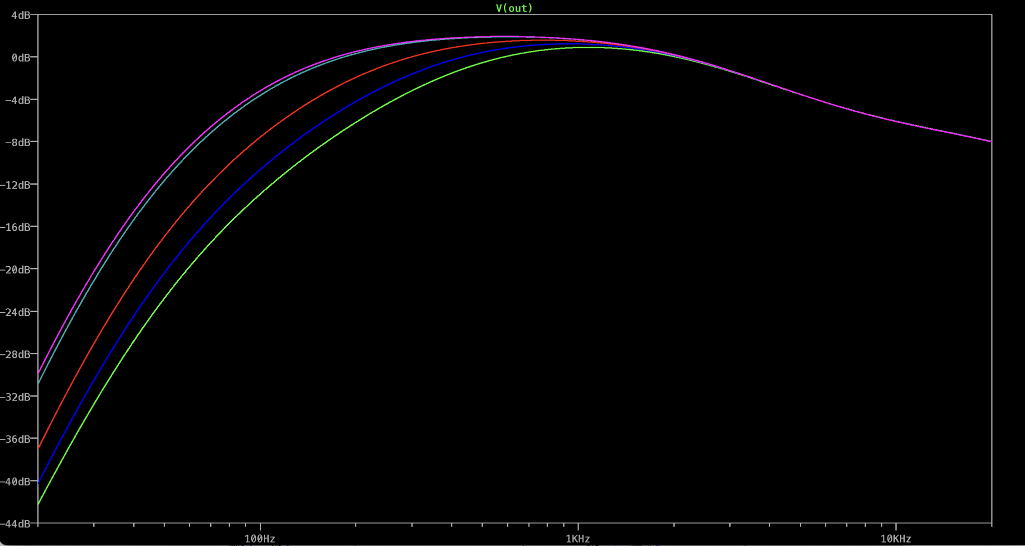
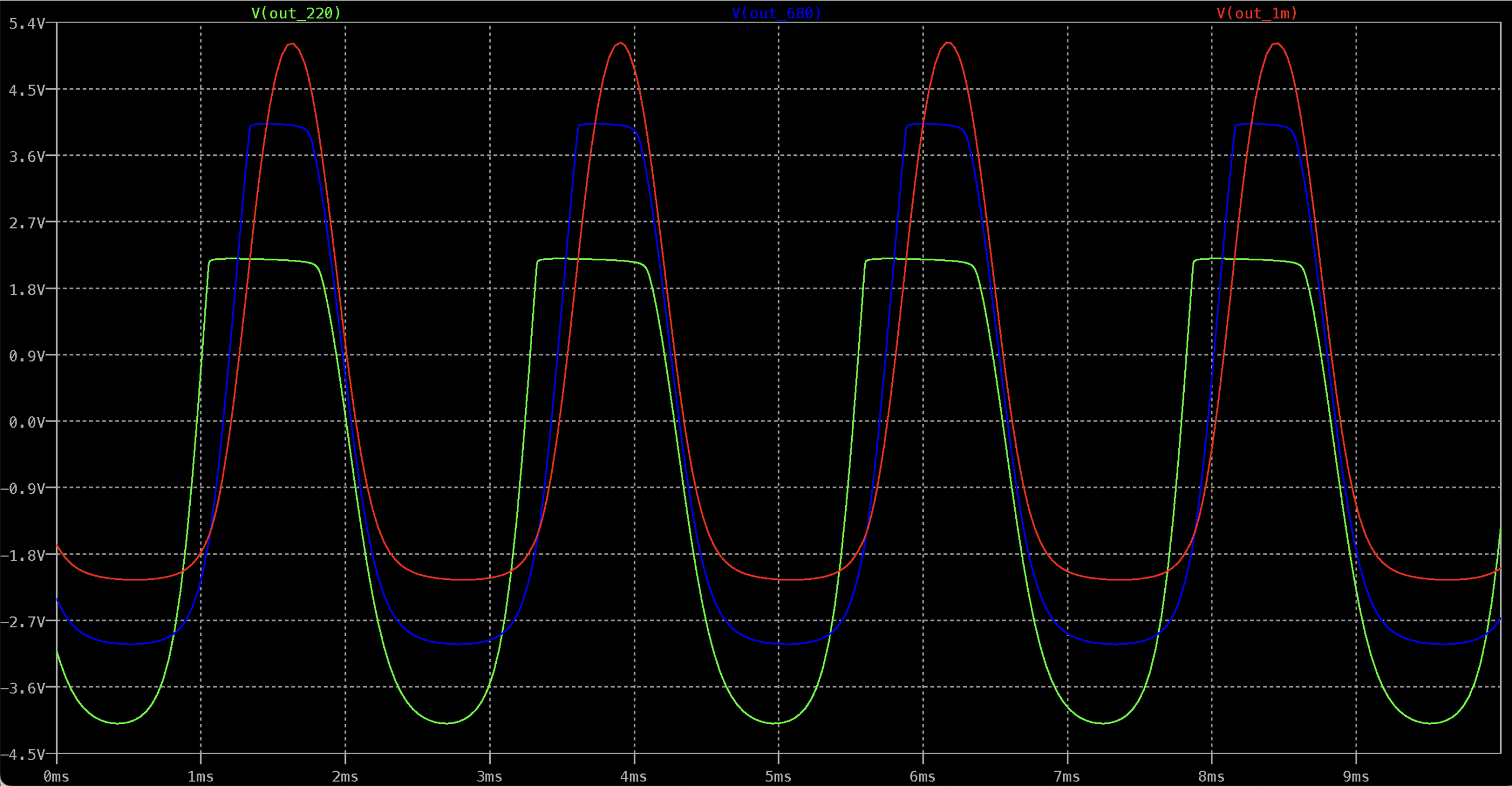
EFFECT OF C3 ON BASS RESPONSE

R1 / R2 BIAS RESISTORS
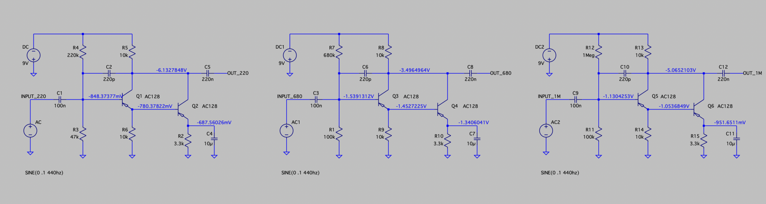

Apart from the output level, the resulting wave is a little different for each one, and of course 100n/47k vs 100n/100k form different high pass filters, resulting in a slight difference in low end. This can be further tailored with the value of C3 (the capacitor on the emitter of Q2).
MKIII TREBLE N BASS VALUES
{
“@context”: “https://schema.org”,
“@graph”: [
{
“@type”: “BreadcrumbList”,
“itemListElement”: [
{
“@type”: “ListItem”,
“position”: 1,
“name”: “Home”,
“item”: “https://vero-p2p.blogspot.com/”
},
{
“@type”: “ListItem”,
“position”: 2,
“name”: “Tone Bender MKIII component values table”,
“item”: “https://vero-p2p.blogspot.com/2022/12/tone-bender-mkiii-component-values-table.html”
}
]
},
{
“@type”: “BlogPosting”,
“mainEntityOfPage”: {
“@type”: “WebPage”,
“@id”: “https://vero-p2p.blogspot.com/2022/12/tone-bender-mkiii-component-values-table.html”
},
“headline”: “Tone Bender MKIII component values table”,
“description”: “Component values table and analysis for the Tone Bender MKIII and MKIV germanium fuzz pedal, including schematic, board layout, bias resistor options and treble and bass capacitor values.”,
“author”: {
“@type”: “Person”,
“name”: “Andrew Hopkins”
},
“publisher”: {
“@type”: “Organization”,
“name”: “vero-p2p”
}
}
]
}