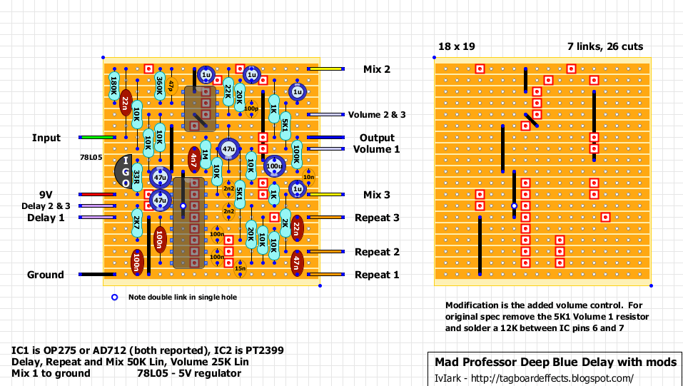
Slightly modified to give you an overall volume control but if you want the standard unit, just swap the 5K1 Volume 1 resistor for a 12K and solder between IC1 pins 6 and 7. Again it’s small enough to fit in a 1590B with some careful measuring.
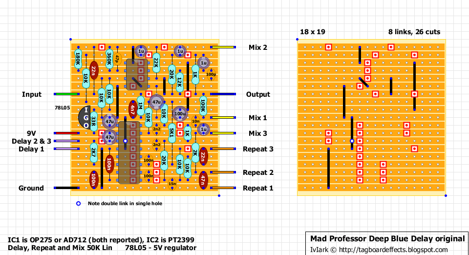
Updated: Delay 1 connects to the PT2399 pin 4, not to ground as shown on the original layout. The connection on the board is Mix 3, with Mix 1 going to ground.
Update 2: Now verified. Note the double link at pin 3 of the PT2399 to pin 4. Both pins need grounding.
Bjorn’s spiel:
There are no noise reduction circuits, which keeps decay of echo as natural as possible.
The direct signal path is short and made with analog amplifiers with no filtering.
There should be no distortion or tone coloration as long as input level is in range below maximum allowed.
The echo signal has a tuned filtering to allow extreme settings without interference.
The delay is specially designed to work well with distorted tone, as this is the most critical application, where delays often fail.
You can use the pedal before or after distortion. As such, it will work exceptionally well on clean sounds where requirements are less stringent, especially in terms of echo bandwidth and repeat formation.
The delay tone has been carefully tuned with lot of attention to the first critical reflection and how the repeats decay.
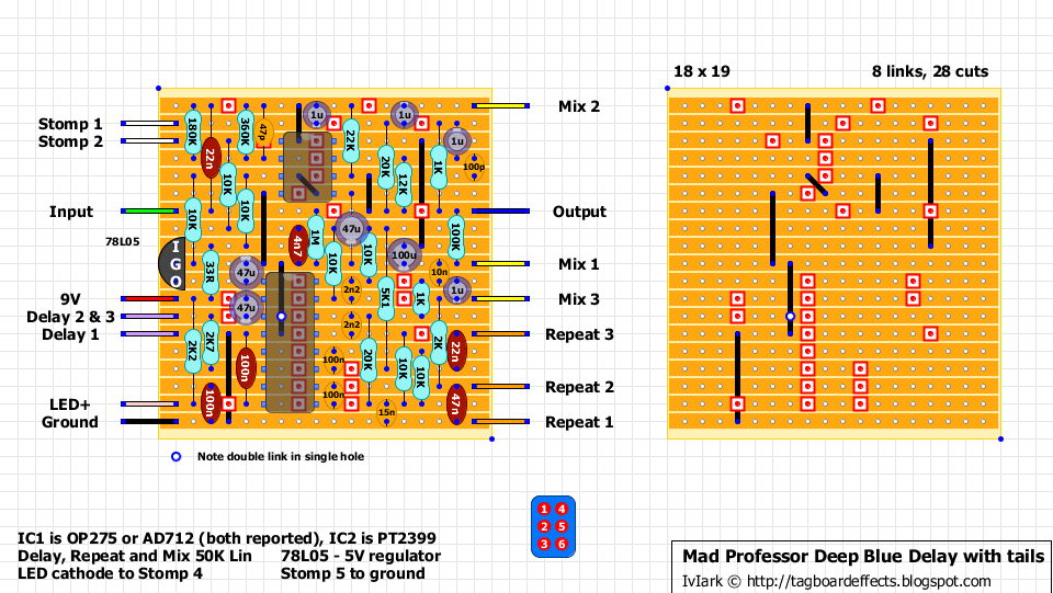
And a requested version with tails. With this version the usual stomp switch wiring isn’t used, and instead the input and output wires go directly to the sockets. The stomp here will cut the signal going into the PT2399 and so when bypassed the output of the PT2399 will continue until the repeats are complete and IC1 will then act as a buffered bypass. It may be a good idea to swap the 12K resistor at pin 7 of IC1 for a 20K trimmer so that the buffered bypass level can be tweaked to perfect unity with your bypassed signal. As another alternative you could add a second stomp to true bypass the whole thing if you prefer, giving you an option of mechanically bypassing as usual, or bypassing with tails when you need to.