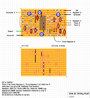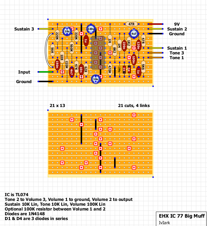
I wanted to try this one out with a quad opamp and so thought I’d put together a couple of layouts, one for the 1977 version and one for the 1978 version with a tone bypass switch.
I have done a version of the 77 with all the diodes laid out on the board, but to keep the width down to allow this to be mounted in a 1590B box I decided to simplify the diode layout, so D1 and D4 are each 3 x 1N4148 diodes in series. They’re small enough to allow you to make these groups of 3 up yourself (and maybe cover them with shrink tubing) without looking unweildy on the board, so I thought it made the most sense to keep the layout as compact as possible.
Both layouts were put together with the TL074 opamp in mind, but if you use a non-fet based quad opamp then the 1M resistor from pin 10 to the supply rail should be changed to 820K.
Layouts were based on analogguru’s schematics but are currently unverified, so if you build this up then please let us know how you get on.