This little circuit is part of DIY pedal designs early beginnings. I first ran into it when I was surfing the early DIY forums in the early 2000s but never really paid it much attention, I wish I had done because it sounds great!
Here’s the original newsgroup posting in which Arsenio Novo presents his circuit idea (from the 4th July 1995!);
“********************
From: Arsenio.Novo@mba.org (Arsenio Novo)
Date: 04 Jul 95 23:04:50
Newsgroups: rec.music.makers.guitar
Subject: New Overdrive Circuit
Organization: MtlNet (MBA.org) MBA [514-465-8524] Brossard, QC
Hi,
I’ve noted that talk on this echo always comes back to the subject of
overdrive distortion. Whether generated by a vacuum tube amplifier or
a transistor amplifier there seems to be undeniable differences to me
as well.
Lately, I was tinkering with an unusual transistor circuit
configuration I had come upon a few years ago and made a few
modifications to the circuit that turned it into one beautiful
screaming “tube-like” overdrive but without the wall of noise these
things usually make. When pushed it even makes that distintive
“zoo-zoo” sound…!!!
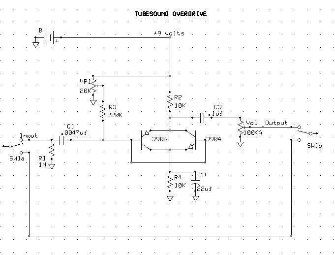
The original circuit was simply a complementary matched pair of
transistors connected so that all the terminals overlapped. i.e. both
bases tied together, emitter of the PNP connected to the collector of
the NPN, and the collector of the PNP connected to the emitter of the
NPN.
This transistor pair is then biased by 2 equal value resistors in each
of the compound legs, one to the positive supply and the other to
ground common. The signal is coupled to the base pair leg and the
output is picked off either of the other 2 legs.
The result is that the above circuit exhibits the behaviour of a
multiplier over a range of signal values. It basically performs a
sin function: in other words a frequency doubler.
This doesn’t have a very good distortion sound though because it is
rather “burpy and buzzy”. However, lately I was toying with the
circuit when I offhandedly decided to try doing something to it just
to see what would result.
After adding a large cap from the NPN’s emitter to ground the thing
went wild on me… WANGO ZE TANGO! SUPREMO DISTORTION! I then
proceeded to refine the circuit a little more and got a better
understanding of what it was doing.
The final schematic follows but first a couple of notes on the
circuit. The “bias balance” trimmer should be adjusted for a
symetrical clipping threshold of the output signal as viewed on a
scope. Short of this it can be easily set by “ear” for the most
sensitivity somewhere around mid-turn.
The input should be driven by a lo-z stage if your electric guitar
doesn’t have a built-in pre-amp. You can alter the emitter capacitor
value in a range from 0.1uF to 1uF in order to obtain various basement
characteristics but I found the indicated value is a good compromise.
The input capacitor should not vary much either though because if it
is made too large the circuit goes balistic and cuts out on the tutti.
The operation of the circuit more closely resembles a vacuum tube than
a diode clipper does because of the strong square law characteristic.
This is due to the negative feedback around both base-emitter pairs.
This feedback accentuates the junction non-linear behaviour manyfold.
Thus each transitor drives the other even harder so that the transfer
curve ends up more logarithmic than is typical of a single transistor.
In other words: the clipping is gradual and not abrupt like it is in
the case of a silicon diode. Typically a lot more 2nd harmonic is
produced as well. As a bonus the waveform folds over on itself when
the circuit is overdriven!
Now in the interest of the common good I donate this design to the
public domain for personal use but retain copyright and reserve all
rights for any commercial purpose. In other words build one for you
and your friend but if you have it massed produced for profit I only
ask a fair share.
Please, do try the circuit and leave any comments in private at my
e-mail address: arsenio.novo@mba.org
****************”

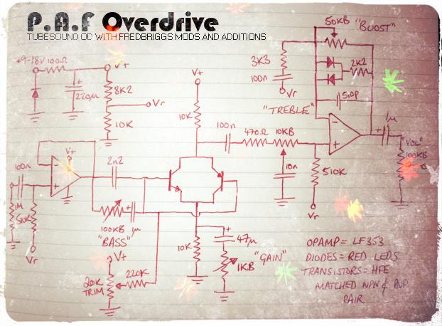
[EDIT] Here’s another few mods I’d like to suggest for this little circuit. Basing these mods on the first schematic of the Tube Sound OD;
“The TubeSoundOverdrive is a nice sounding little circuit. There are a few mods I make to this thing when I build them;
1 – I add in a 100kB (Linear) pot wired are a variable resistor in series after the input cap, this allows you to smooth the tone out, reduce the gain a little and take away some of the cutting highs (in some builds where I don’t want too many knobs I just use a 10-15k resistor instead of the pot),
2 – I raise the input cap to 22/33nF (depending on how much bass is wanted),
3/4 – I add in a 4n7 cap in parallel to a 500kA (Log) volume pot, this further reduces the overpowering top end,
5 – Instead of using a 10uF bypass cap on the 10k resistor from the NPN transistors emiitor I use a 470nF cap as the bypass, I then wire up a series configuration of a 10uF cap with a 4k7A (Log) pot, this is then wired in parallel to the 470nF bypass cap. This mod allows you to control the overall gain/low end saturation of the build. With this mod you can go from treble boost right through to a full range boost.”