
Let’s build the Madbean Turnabout (a.k.a. JHS Andy Timmons clone). I got the chance to play the JHS @ (Andy Timmons) at the Chicago Music Exchange a while back and it sounded pretty freaking good. It had a nice, thick overdrive/distortion and the clipping options made pretty drastic changes which was cool. So when a vero layout based on the pedal showed up, I knew I had to make it. I’ll go through the fairly simple circuit theory that this pedal uses and then quickly go over my process for building this pedal. Lastly, I’ll say a couple words about how knowing the theory behind this pedal helped me to troubleshoot an issue I had.
Please note: the circuit used here is from the Madbean Turnabout which is similar to, but not exactly the same as the JHS @. There are only two significant differences which I’ll point out as they come up.
The Theory
Something I like about this circuit is that it’s pretty straightforward from a theory standpoint. Nothing crazy, just basic building blocks that result in great tone. We’ll be using the schematic from the Madbean website for this but taking it one block at a time. I’ve gone ahead and marked up a copy of the schematic based one what the blocks are for our analysis here:
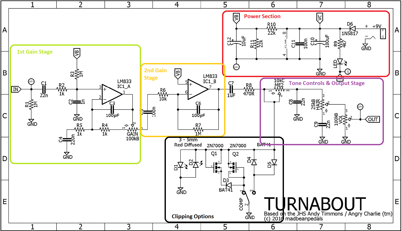
Power Section
This is a pretty standard power section. The 100uF and 10uF caps do some DC filtering to get rid of residual ripple from the power supply. A pair of 22k resistors forms a voltage divider to bias the op-amps for the signal path.
1st Gain Stage
The first gain stage is very simple. It’s a standard non-inverting op-amp configuration like you might see in a Tubescreamer. The difference here is that it doesn’t include diodes in the feedback look for clipping. A low pass filter, centered at 723.8Hz is made with R5 (1k) and C4 (220nF) which could be fun to play with in order to change up how the mid frequencies are affected.
If you look at the gain range for this section, then using the equation for a non-inverting op-amp we get 2 at the low end and 101 with the drive knob all the way up.
2nd Gain Stage
The second gain stage is another basic building block. It’s set up in an inverting op-amp configuration. In this case R6 and R7 set the gain for this stage at 100. Nothing super fancy is happening here, you could tweak those resistors to mess with the gain but it’s probably not worth doing since you already have the gain knob in the first stage.
Note: The coupling capacitor, C7, is different between the Madbean and JHS pedals. In the JHS version this is a 2.2uF cap as opposed to the 1uF in this circuit.
Clipping Options
The clipping options on this pedal are pretty cool. The pedal uses an on-off-on SPST toggle switch. In the center position the contacts of the switch don’t connect. Since the LEDs are outside of the switch, they are able to conduct and clip the signal. When the switch goes to either of the other two positions, the diodes and/or MOSFETs have a lower clipping threshold than the LEDs so they conduct and clip the signal instead of the diodes.
Note: This is just how the Madbean Turnabout configures it. Changing clipping diodes is a great way to achieve new sounds from a circuit. The JHS Andy Timmons has a similar 3 way toggle, but they use LEDs for their 50W mode, BAT41 diodes for the 25W mode, and no diodes for their 100W mode. You can try all sorts of combinations with your own setup. Just make sure they have lower forward voltages than whatever the combination in your middle position is or the middle position will start clipping first.
Tone Controls & Output Stage
Then there’s a really basic volume control at the output which is simple a potentiometer set up as a voltage divider. The schematic and layout shown here calls for a 100KB pot but I’d highly recommend a 100KA for a better sweep.
Summary
The Build
For this one I decided to go ahead and use veroboard. You can fab your own board from the Madbean site if you’d like, but I had some extra vero laying around so I figured that would be faster and easier for me. I used the layout from tagboardeffects as seen here:
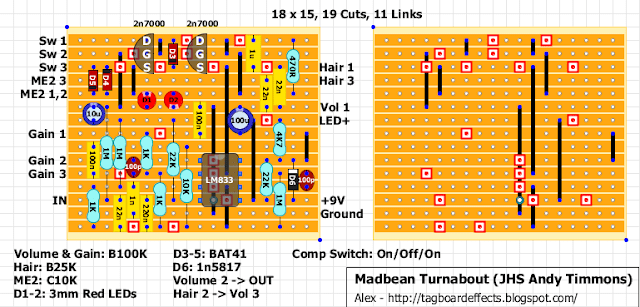
I went with my usual procedure for building a very layout:
- Cut board to size
- Cut traces
- Add in links
- Resistors, diodes, sockets
- Small caps (MCC, film)
- Large caps (box and electrolytic)
- Offboard wiring to pots and switches
Then I quickly checked it to make sure it passed signal and did distortion stuff using a basic test rig (power jack with leads, input/output jacks with leads all connected on a breadboard). When it fired up I threw it into a box and soldered everything up (jacks, switches, LED, power).
Here’s a picture of my vero part way through.
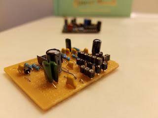
You’ll notice that there’s two layers of sockets where some of the diodes go. That’s because I’ll break off the sockets I need and stick them onto a larger piece to keep them in line with each other when I solder them.
Troubleshooting
References
- Op-amp equations – http://www.electronics-tutorials.ws/opamp/opamp_8.html