I found this schematic a little while ago and thought I might give it a try, as I’ve been looking to make a single band parametric equaliser, in this case, based on a State-Variable Bandpass Filter. It’s supposed to be from a Japanese textbook, but I’m not sure of its origin. It looks remarkably similar to a schematic in an article published by John Roberts in Popular Electronics back in 1979.
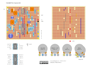
PARAMETRIC EQUALISER ORIGINAL – VERO LAYOUT

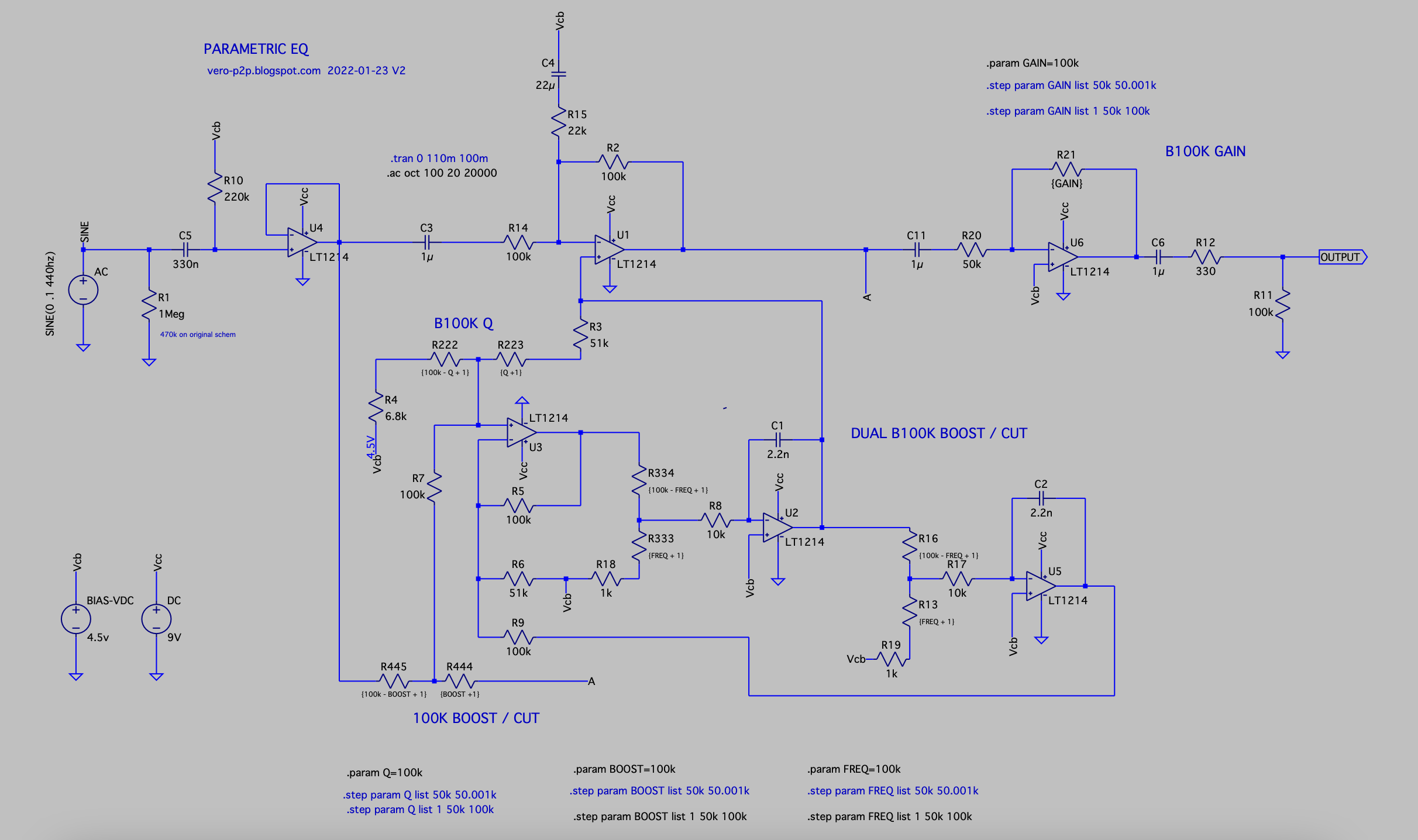
PARAMETRIC EQUALISER ORIGINAL SCHEMATIC

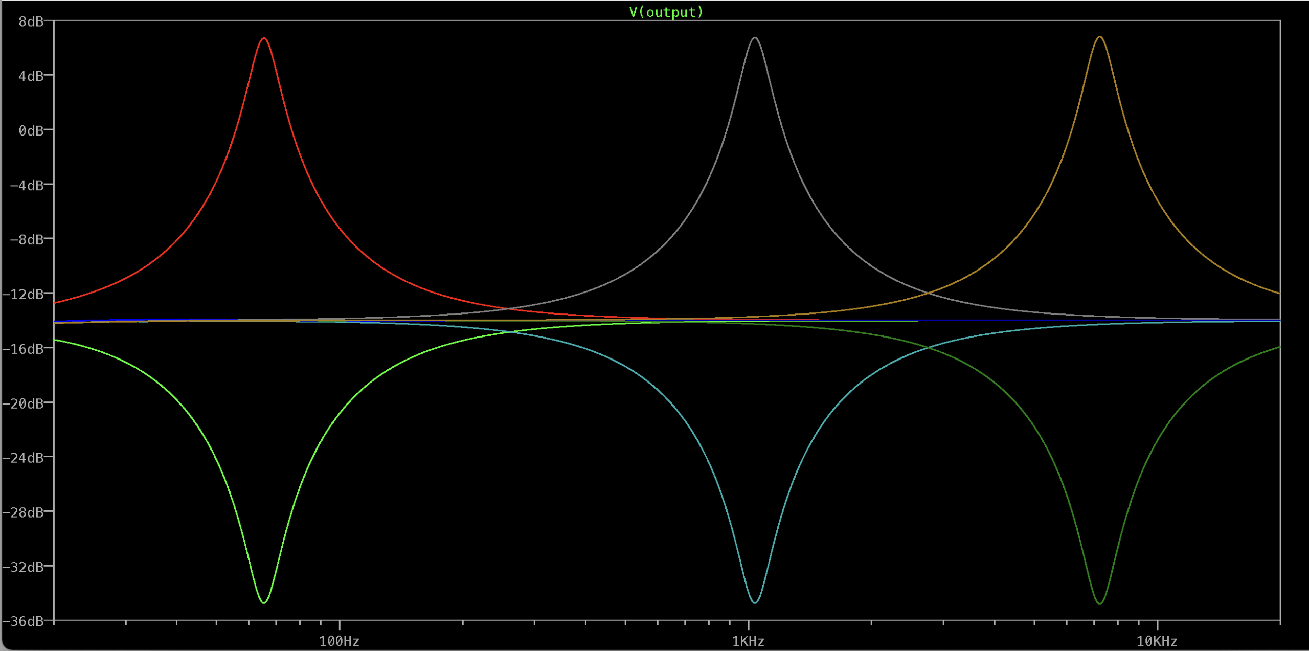
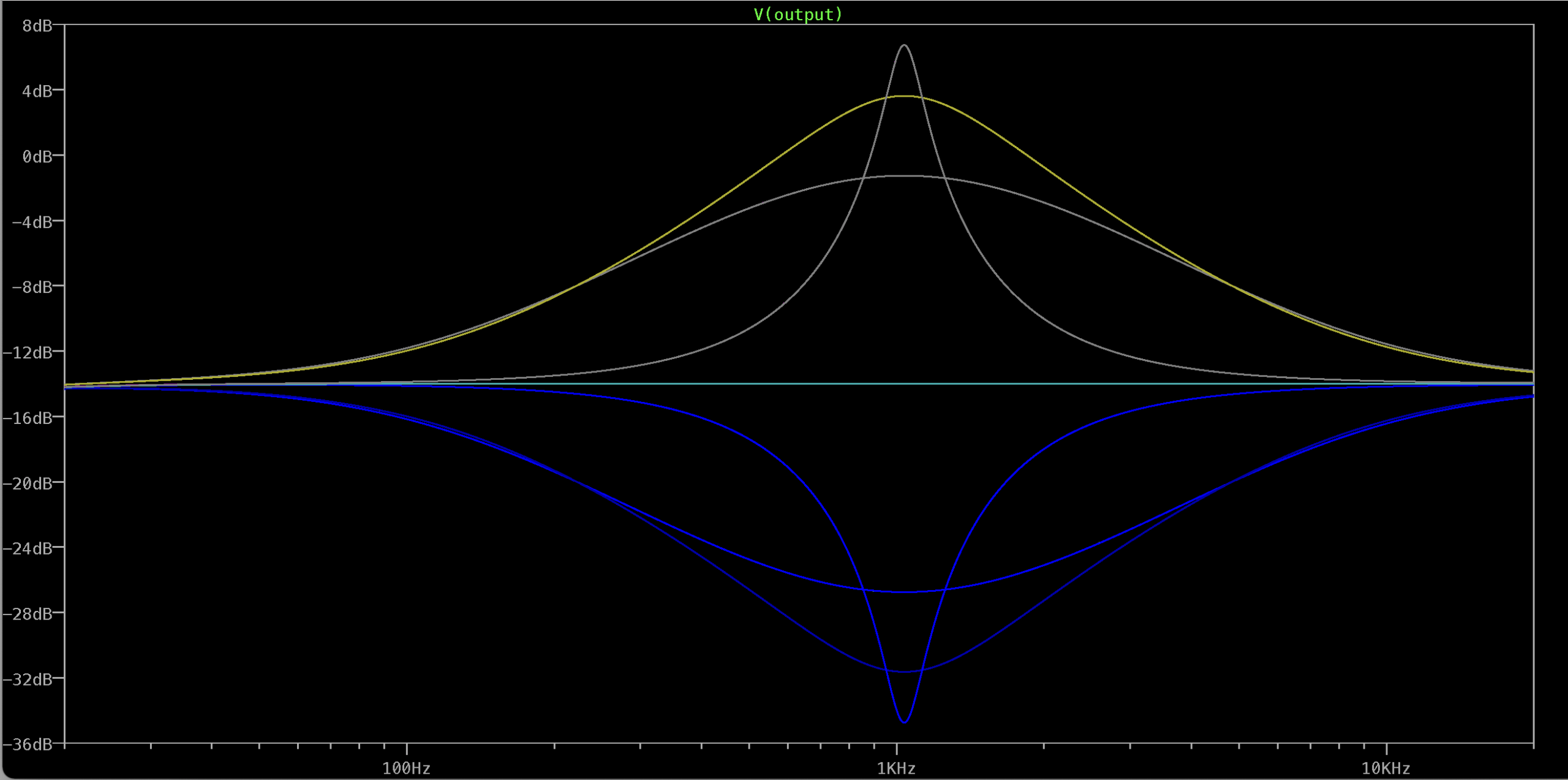
It has a broad frequency range of 70hz – 7khz, and approx 10db of boost and cut. The Q also has a decent range, although I wouldn’t mind making it a little tighter on the most extreme setting.
I added an extra opamp stage, as the stock version doesn’t have a volume control, and it there would be a volume drop when cutting the signal. I also like the idea of being able to hit whatever is following the EQ hard with a spike in the frequency range.
PARAMETRIC EQUALISER – MODDED SCHEMATIC