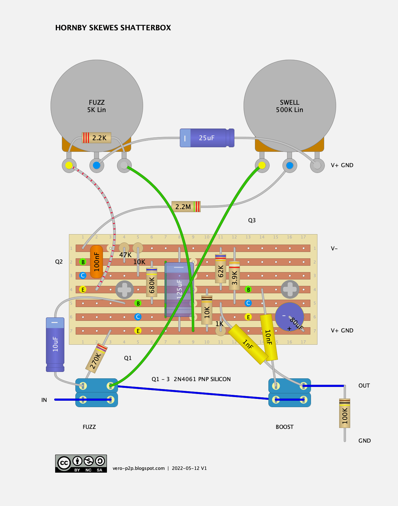
Continuing with the Hornby Skewes theme, time for the Shatterbox – original layout below using the old school large format 0.15″ stripboard. Although I’m not sure if I actually want to build one this way… apart from all the off-board components, it’s PNP silicon, which is annoying having a positive earth circuit with none of the benefits of germanium transistors.
HORNBY SKEWES SHATTERBOX – ORIGINAL 0.15″ VERO LAYOUT

Photo from freestompboxes for comparative purposes below – a thread can be found here. Scroll down for the rest of the photos and the schematic on the FSB thread, as it actually starts with someone building one (pinkjimiphoton), not liking it and coming up with an improved design.
The original design has a 100k resistor to ground across the output jack, subsequently affecting all signal through the pedal – so this is not in the true bypass camp as it stands. It will affect your signal, whether it’s on or off.
I suggest you modernise the switching if you choose to build it, and while you’re doing that, you may as well make it NPN and add some LEDs. Just remember to flip the polarity of the electrolytic caps if you do.
