Like most people, I’ve never even seen an original MKI in the flesh, so I’m relying on online references for this. The references below all relate to original MKIs – or pedals that are said to be direct replicas of originals built for Sola Sound.
Please feel free to comment and point me in the right direction if you think there’s something I should correct or add – ideally with a link to a reference somewhere. Unfortunately, there are only a handful of MKIs left in existence, so new reference material is difficult to come by.
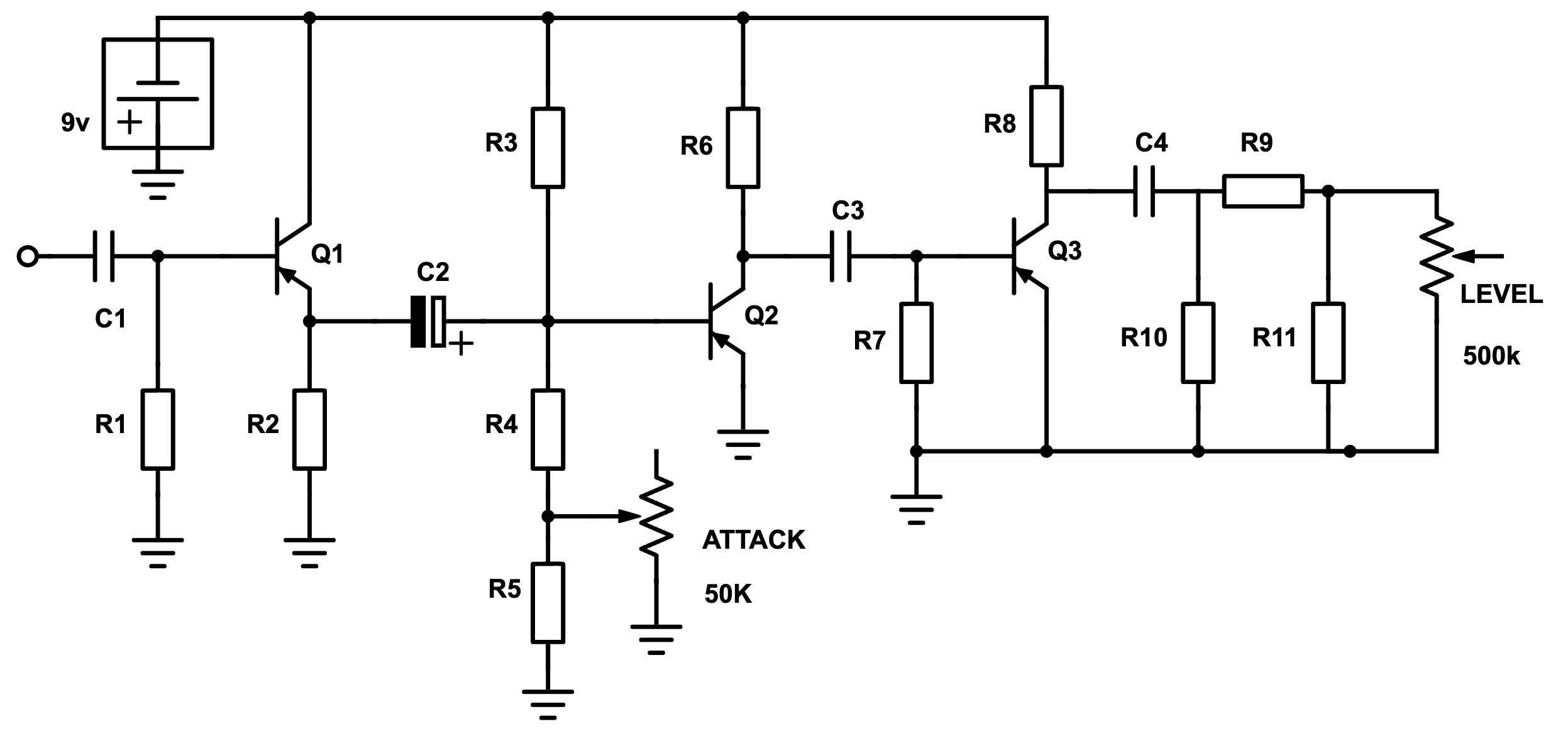
GENERIC MKI TONE BENDER SCHEMATIC
This is the basic schematic for all MKI Tone Benders, with or without R5 & R11and C3 is sometimes electrolytic. Yes, I know the pots were 47k and 470k, but hey…

TONE BENDER MKI COMPONENT TABLE
Link to table in google sheets (probably easier to view by opening the link)
TONE BENDER CIRCUIT VARIATIONS
I’m certain that anyone who has found their way to my blog has seen the Dave Main schematics, the gospel for Tone Benders. As it happens, there seem to be some other values floating around out there from original MKIs that are not well documented – hence this post.
Apart from a number of small variations that are to be found, I believe that there are three basic types of MKI circuits that roughly match different production periods – for want of better names and to match the existing schematics out there, they are the;
- Wooden box
- Gary Hurst
- Sola Sounds
There are variations even across these three – despite the variations, they can still be grouped together largely based on capacitor values and production methods.
The Wooden Box
The wooden box is the earliest of all Tone Benders – and of course very few still exist. This is what I think sets them apart from others;
- Constructed on vero board & gooped
- 3 x OC transistors – exact type unknown, thought to be OC75 or similar
- 22n input cap, 22n output cap and 2 x 25u coupling caps
- 33k resistor across Attack pot
The wooden box circuit is the basis for a lot of Stu Castledine’s MKIs, as he happens to own one that was rehoused in a metal enclosure at some stage. The information above is based entirely on Stu’s MKI builds – there are some minor variations between builds, so take this as general guidance only.
The 22n input cap and the two 25u coupling caps let a lot of additional low-end signal through at the start of the chain, which is then reduced by the smaller output cap.
Gary Hurst
This is the next evolution from the wooden box when production moved into the metal enclosures for perhaps obvious reasons.
- Point to point on phenolic board
- 1 x Mullard OC75 & 2 x Texas Instruments 2G381 transistors
- 10n input cap, 2 x 25u coupling caps and 100n output
- 33k resistor across the 50k Attack pot
- 47k resistor across the 500k Level pot
The two large coupling caps allow a bit more bass through – this is certainly noticeable compared to the next version which is the Sola Sound.
Sola Sound(s)
The last of the line – this is when Sola Sounds appears on the front of the metal enclosure. Very similar to the previous, but with a few changes to biasing and coupling caps.
This version has a more focused mid-range, than the other two as a result of the 100n coupling cap (C3) – perhaps a little more aggressive sounding.
COMPONENT VALUE VARIATIONS
C1 – INPUT CAP
All MKI Tone Benders have a 10n input cap right? Apparently not. Stu Castledine’s very early version has 22n input and output caps. Dave Main’s Phoenix has a 68n input cap and more recently, one has appeared with a 4uf cap – did it leave Macari’s like this, who knows? The MKI based Marshall Supafuzz also used a large input cap, so maybe…
These changes both make a significant difference to the sound, as more low-end is making to Q2, which is where a lot of the magic happens.
C3 – COUPLING CAP TO Q3
Values spotted: 50n, 100n, 25u & 40u
HPF
40u 8k2 = 0hz
25u 8k2 = 1hz
100n 8k2 = 194hz
50n 8k2 = 388hz (maybe)
NOTE: This is just the RC filter calculation – when a leaky transistor is added, these values will increase by varying degrees. Check out the detailed calculations here
It’s the change from a large electrolytic cap to a 100n cap that really makes a difference. The higher cut-off of the HPF before that last transistor has a noticeable effect on the tone.
C4 / R10 – OUTPUT CAP / HPF
C4 and R10 form yet another HPF – most MKIs have 100n here, with either a 47k or 56k resistor for R10.
HPF
100n 56k = 28hz
100n 47k = 34hz
47n 56k = 60hz
22n 47k = 154hz
22n 33k = 219hz
The 22n output caps are only found on the wooden box version, which is paired with larger input and coupling caps – the HPF is removing some excess bass. It does not sound thinner by any measure.
TUNING NOTES:
These are my notes from breadboarding and spending time testing a lot of transistors + a bit of reading on the internets. Your results may vary. If your MKI is not sounding good, the first place to look is the transistors, and the bias of Q2.
Q1
Just a buffer really – there are minor differences with any transistor that will work in this position. Need some leakage here. OC75s usually leak like sieves.
Q2
Spend time getting Q2 right – it’s perhaps the most important transistor in the circuit
Full attack – voltage will drop from close to 9, down to about 5 (in very round figures).
Q3
Affects the general character of the fuzz, including high-frequency content. Lower gain and leakage reduces fizz and scatty note decay (and can act as a noise gate). Despite Q2 doing most of the work, Q3 is still pretty important.
BIAS RESISTOR R3
Anywhere between 180k – 470k have been used. Adjust to taste and your transistor stock.
ATTACK POT
Not unlike the bias resistor – if you have to tune it to taste with R5, there’s nothing wrong with that. Smaller bias resistor (R3) can mean smaller pot value. Log pots are recommended by some.
Parallel resistance for the Wooden Box & Gary Hurst versions
50k pot + 33k resistor = approx 20k
The Sola Sounds version does not have the additional resistor across the 50k Attack pot.
Do not expect a nice even sweep of fuzz across the range. It can happen, and it’s nice when it does, but sometimes it doesn’t work out like this (log pots often fix this). Note the video below for a demonstration of this, using original Tone Benders.
SYSTEM MKI TUNING TIPS FROM SEEKER ELECTRIC EFFECTS
So nice that this was shared
REFERENCE VIDEO BY GRAHAM GREEN – ORIGINAL TONE BENDERS
ADDITIONAL REFERENCES: RECENT BUILDS FOR MACARI’S (LATE 2022)
STUART CASTLEDINE OF CASTLEDINE ELECTRONICS
IAN SHERWIN OF GHOST EFFECTS – GHOST V2
DAVID MAIN OF D*A*M – THE PHOENIX
STEVE WILLIAMS OF PIGDOG – SYSTEM 2
And if you want more, check out https://www.youtube.com/@pinstripedclips