Not a huge amount of variation on Zonks in terms of component values, and at one stage this was all on the MKI table, but I decided to split the two.
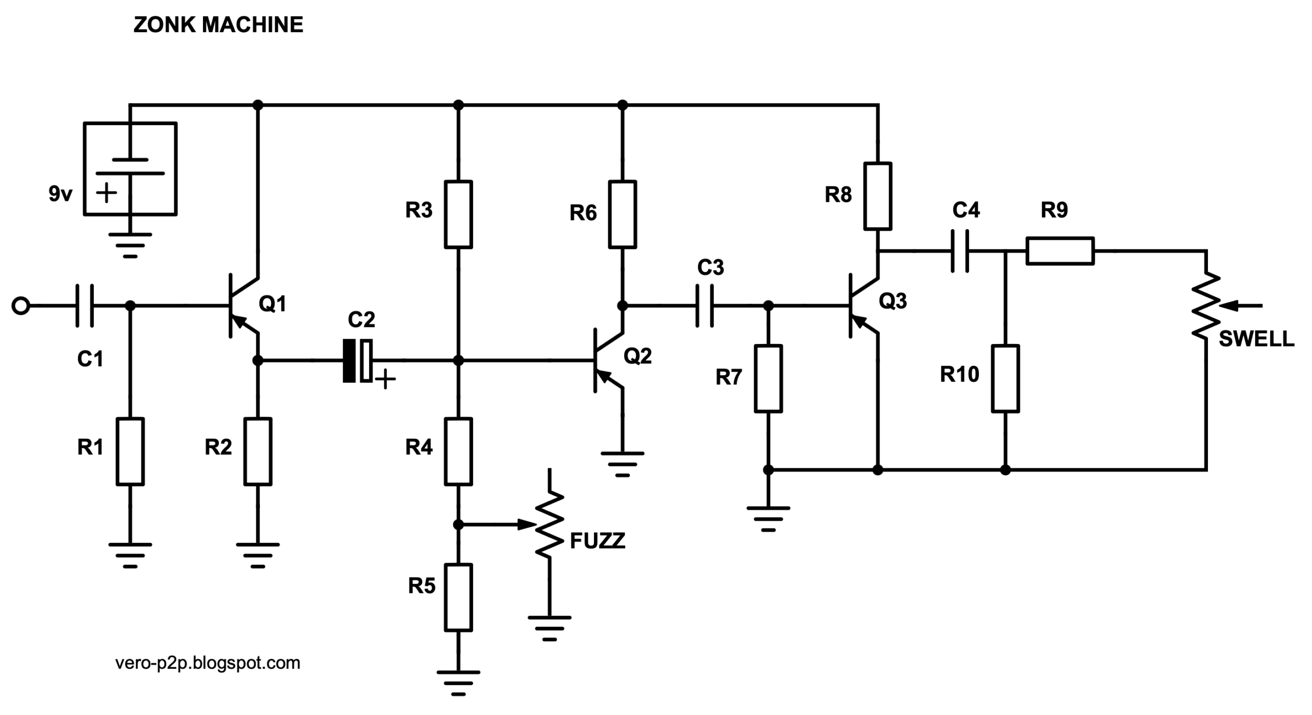
ZONK MACHINE SCHEMATIC

ZONK MACHINE COMPONENT VALUES
BUILD NOTES
In my experience, the Zonk can be a little easier to make than the MKI in terms of transistor selection, and just getting a sound out of it – but it’s still not one to rush into without a good stock of transistors to test. If it sounds thin and nasty, it ain’t right yet.
Transistors
Q1 needs leakage to work. Q2 doesn’t need leakage to work, but it uses an OC75, which are usually quite leaky compared to other transistors. Q3 should also need leakage to work, but it has an OC44 here, which are generally quite low in terms of leakage – this is partly where the gated sound comes from.
A good way to test Q1 is to play through it on the breadboard. Just take the output directly from the 22u cap (disconnect the next stage) and see how it sounds. It should sound clean and sustain. Listen for noise. Any noise here is just going to get a lot louder.
For Q2 I like to bias it so when the fuzz is turned all the way down, it’s either not working at all, or barely working. Then the pot will have some range.
Dave Main of D*A*M fame was kind enough to share some voltages and transistor hfe on a schematic, which is as follows.
Q1 Texas Instruments AO2650 hfe 30
Q2 Mullard OC75 hfe 156
Q3 Mullard OC44 hfe 69
Voltage on Q2 collector
-5.1v on full fuzz
-9.6v at zero
Most batteries start life at 9.5v so I have no idea what kind of freak battery Dave had plugged in to get -9.6 volts. Anyways, it will be a high voltage in any case, a range of -5 to -7v would be pretty normal.
And here’s another set of quite different readings from an original Zonk, care of acidfuzz on freestompboxes. Great to see some leakage measurements as well.
Q1 Texas Instruments AO2650 Hfe 180 leakage 0.12mA
Q2 Mullard OC75 Hfe 78 leakage 0.29mA
Q3 OC44 Hfe 58 leakage 0
and here’s a demo, of what might be the very same pedal, as the video is provided by acidfuzz.
Input capacitor
The 1nf input capacitor is really the standout component value on a Zonk – this is really what sets it apart from the MKI Tone Bender. In the video demo above, the Zonk sounds quite fat – it’s not easy getting this tone. I’ve found that a higher hfe Q1 helps and in some cases a lower gain Q2. This is not a hard and fast rule by any means.
If your Zonk is sounding a bit thin and nasty, it’s not the end of the world if you increase the size of the input cap until you get it to a place that you’re happy with. Try a 3n3. There’s a lot of builders out there that offer this circuit with a MKI switch, which basically swaps or adds another input cap to increase the value to something like a MKI (10nf).
The sizzle
The what now? Zonks sometimes have an annoying sizzle on the decay, some people say it sounds like bacon cooking, and you don’t really want that – or maybe some of you do? Some sizzle is not unusual on the decay of a MKI style circuit, but the Zonk can have way too much at times.
First, try different transistors – I’ve found lower hFE on Q2 to be helpful. If you can’t fix sizzle with transistor swaps, try a low value cap directly on the input of the circuit. You want something big enough to reduce the sizzle down to manageable levels, but not so big that it changes the tone too much, although this can sound kind of cool, it’s a bit like a cocked wah sound if you go too big. A 1nf cap often does the trick without affecting the sound.
ZONK RESOURCES;
- Fuzzboxes.org for a bit of Zonk History
ZONK HYBRID READING
Voltages supplied by Acid Fuzz (very kind of him to share)
Trimmer set to about 152k. Here are the voltages at ~70°F with a 9V battery:
1/2 “FUZZ” Full “FUZZ”
Q1:
C -8.98V -8.95V
B -.707V -.715V
E -.656V -.676V
Q2:
C -7.16V -3.632V
B -.643V -.672V
E -0.1mV -0.1mV
Q3:
C -7.99V -7.51V
B -51.7mV -51mV
E -0.1mV -0.1mV
Another video from the acidfuzz series – hybrid Zonk repair and demo