While on the JHS thing, I noticed this booster and thought it looked interesting. The output switches between filters to allow for treble and bass boost, unlike most other boosters where it all happens at the input.
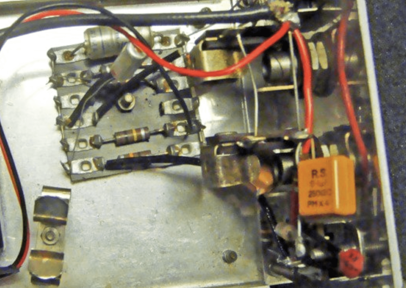
Very few seem to be around, as I could only find one photo of the internals and one video demo. The schematic still has a couple of assumed (but working) values, which are explained below and marked on the layout.
There’s a bit of off-board wiring, which is how the original was built – and no volume control.
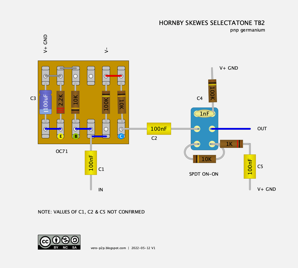
JOHN HORNBY SKEWES SELECTATONE TB2 – TAG BOARD LAYOUT
Image credit: Effects Database https://www.effectsdatabase.com/model/jhs/selectatone#
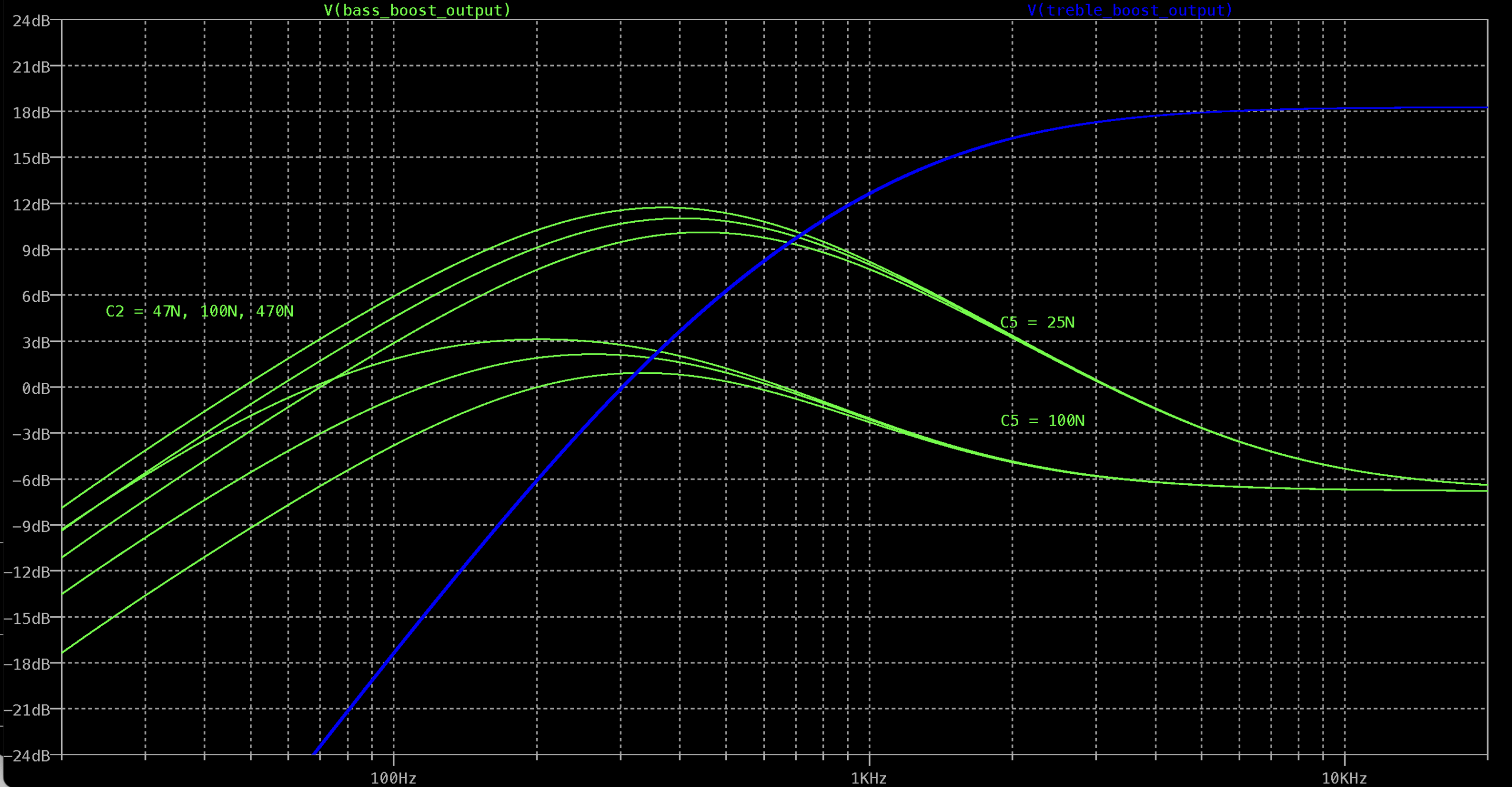
LTSPICE RESULTS
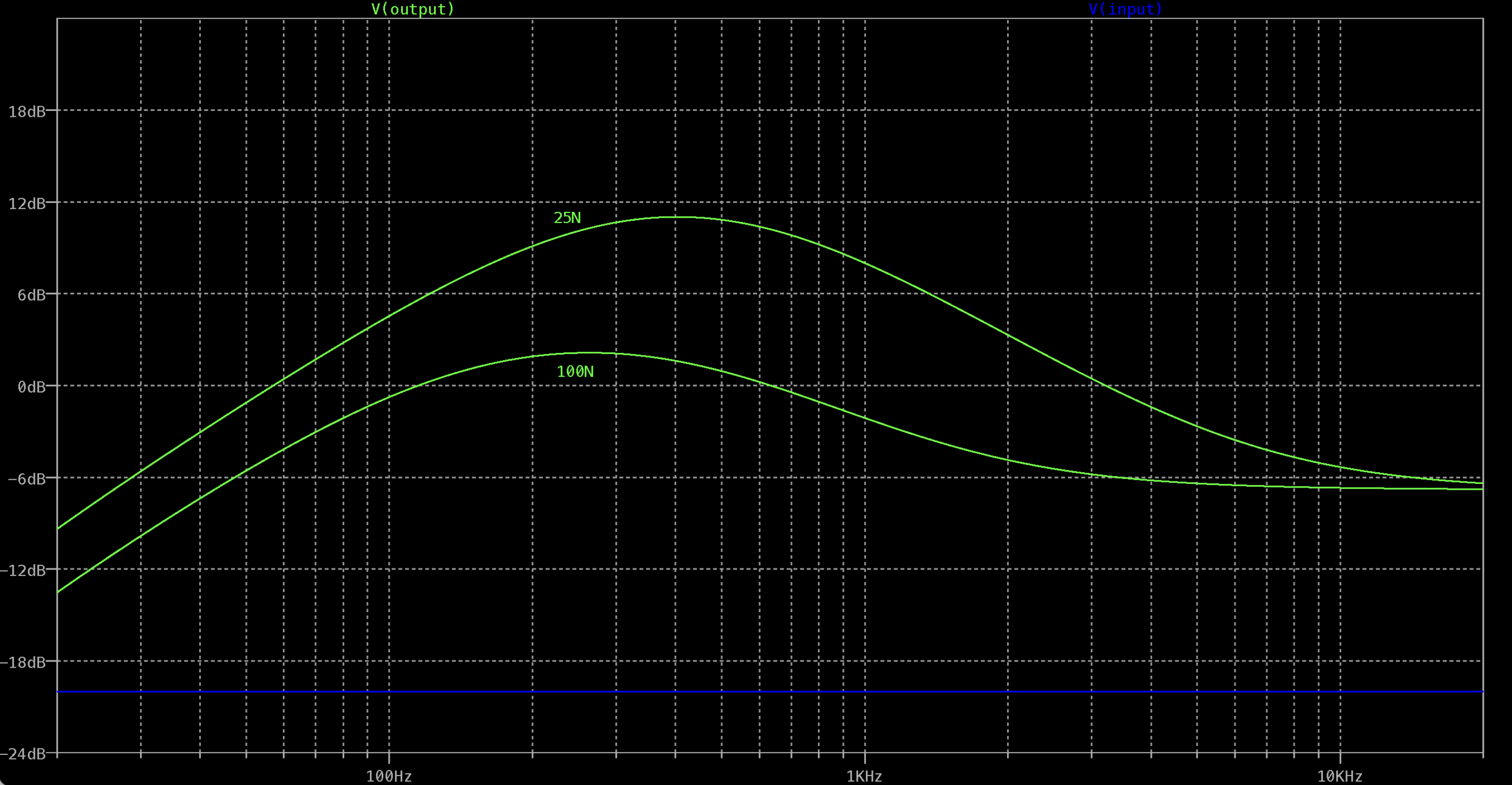
Both with 100n for the input cap (C1), and the cap linking the treble bass switch (C2).
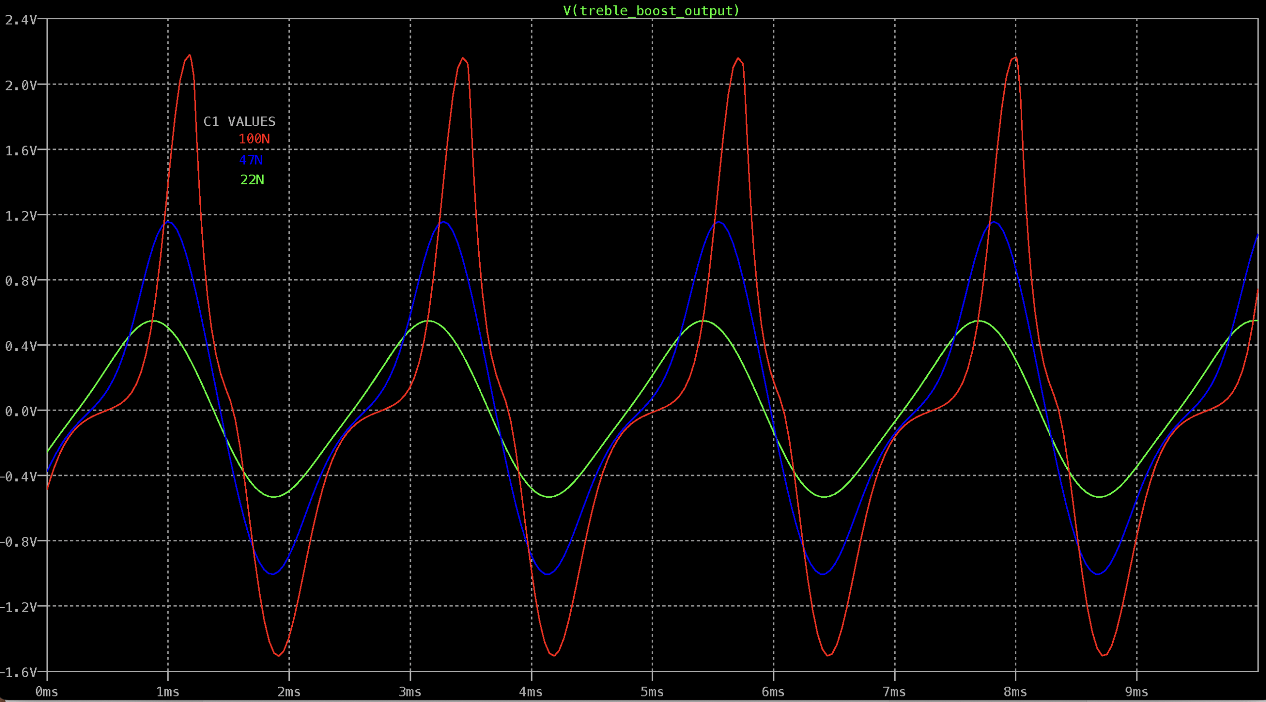
Changes to the 100n caps (C1, C2) mentioned above have almost no impact on the frequency response of the treble boost (right down to 22n), so tweaking these caps is more around tweaking the bass boost to your liking, and there will be some changes to how it distorts as well.
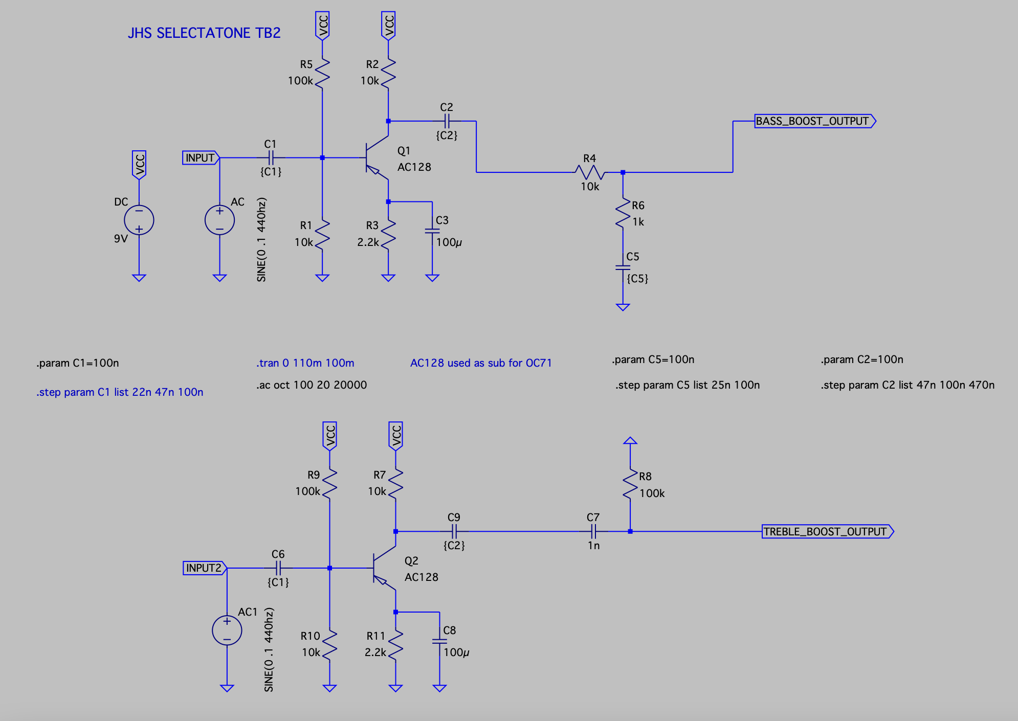
I split the circuit into two for bass and treble boost, as switches are painful in LTspice – simple SPDT / DPDT switches don’t exist.
For nerdy folks familiar with spice, here’s what I was doing (schematic below).
Short story for lesser nerds, a smaller C5 cap in the bass boost section raises the boost level and shifts it towards the mid-range. C2 tunes how much low-end roll-off there is. i.e. you might want a low-mid boost without the flabbiness of too much low-frequency content.
C1 impacts the response, affecting how the transistor distorts, so it’s worth trying a 47n in there and a 100n.
Basically, breadboard it and play with C1, C2, and C5.
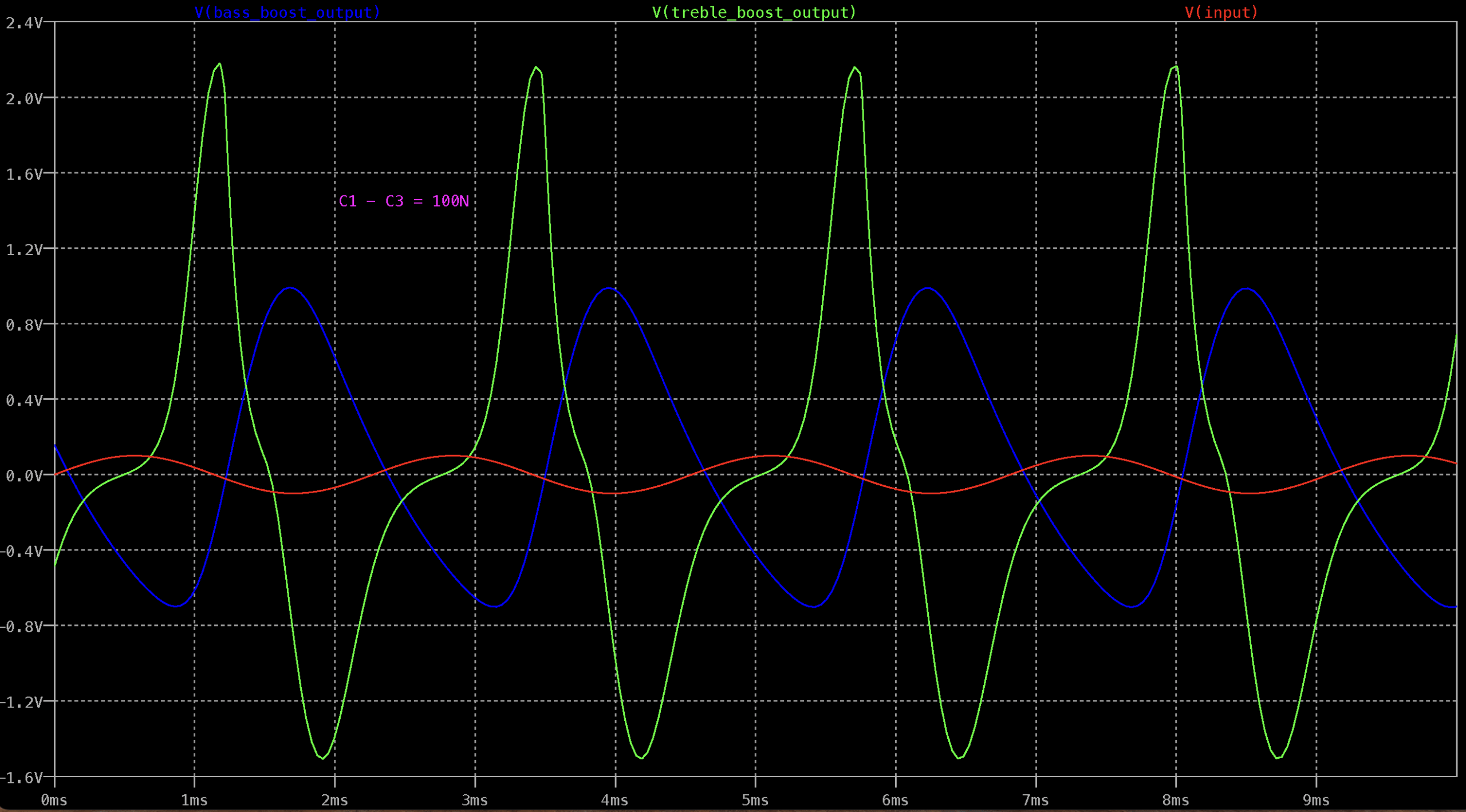
Treble boost vs Bass Boost
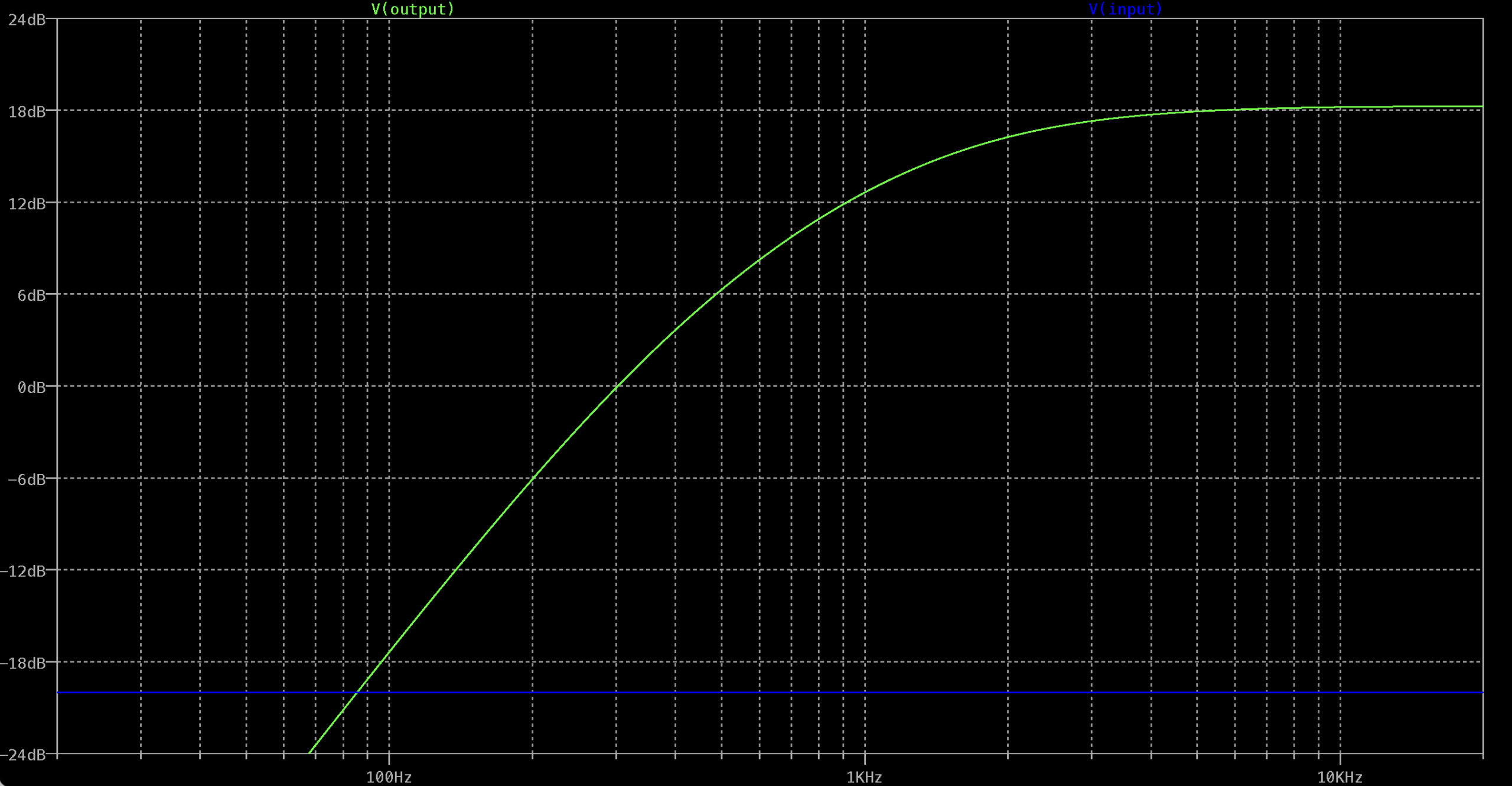
Input cap variations effect on the Treble Boost output
VIDEO DEMO
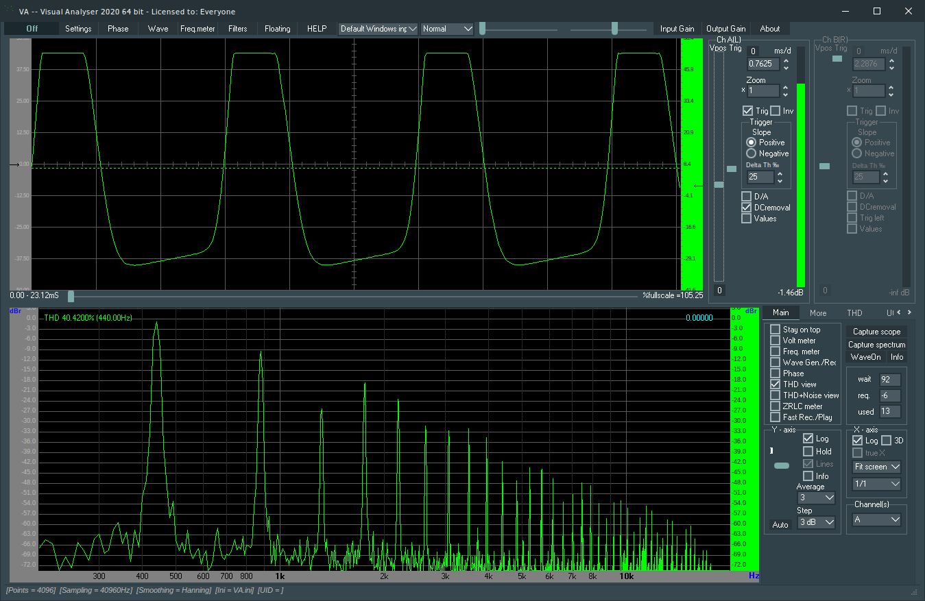
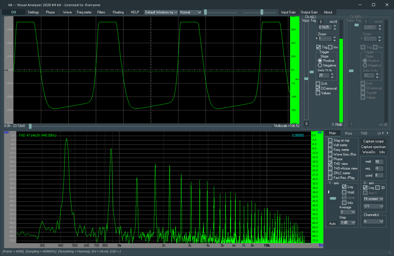
OC71 vs 1T308 TRANSISTORS
Spot the difference? Someone had a question in the comments, so I thought I’d quickly breadboard it for a look – note that this is from the 100n cap on the output, not after the high pass filter.
So turns out they look almost identical, and voltages also measured about the same.