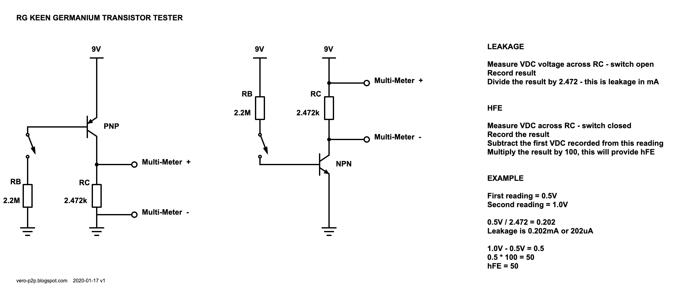
If you haven’t heard of this before (which seems unlikely), here’s the original RG Keen article, which explains how it works. I use a spreadsheet set up with the calculations ready to go for testing; there’s also an online calculator here.
- Be prepared to see the voltage fluctuate a lot while the transistor stabilises. Don’t wait too long though, as you will be there forever – it may never stop!
- Handle the transistor as little as possible with your fingers, as the heat will transfer
- Different environments will provide different results – this is very temperature dependant.
- With all methods, the test results will vary, depending on the method used. Why? Without attempting to explain the math that I don’t fully understand, hFE varies with the current applied to the base. Different methods apply different currents, so results will differ.

LEAKAGE TABLE FOR RG KEEN METHOD
TESTER BUILD
I recently purchased a small multi-function tester, and while it’s great for so many different measurements, I wasn’t completely happy with the leakage results on germanium transistors – maybe it’s just not what I’m used to…
I’ve been using a tester that I built using a layout from Guitar FX Layouts and while it works, it’s very small, and I found that the transistor socket got a bit loose over time. It was just a bit fiddly for me.
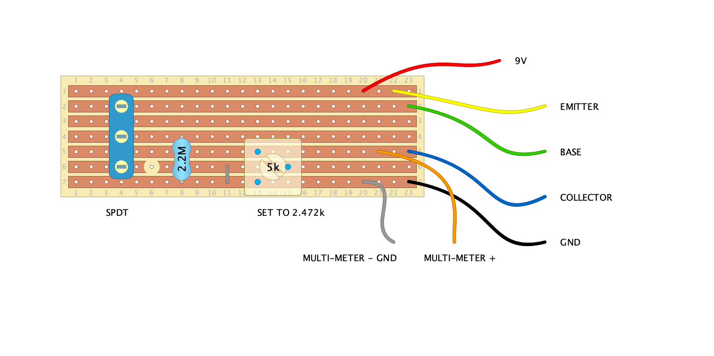
So today, I built something a bit more robust from some scrap 0.15″ vero, I kind of worked it out as I made it, so the layout below is not an exact match.
- Pins to insert in a breadboard rather than use a socket
- The switch is mounted through the board, and I used a trimmer for biasing the collector
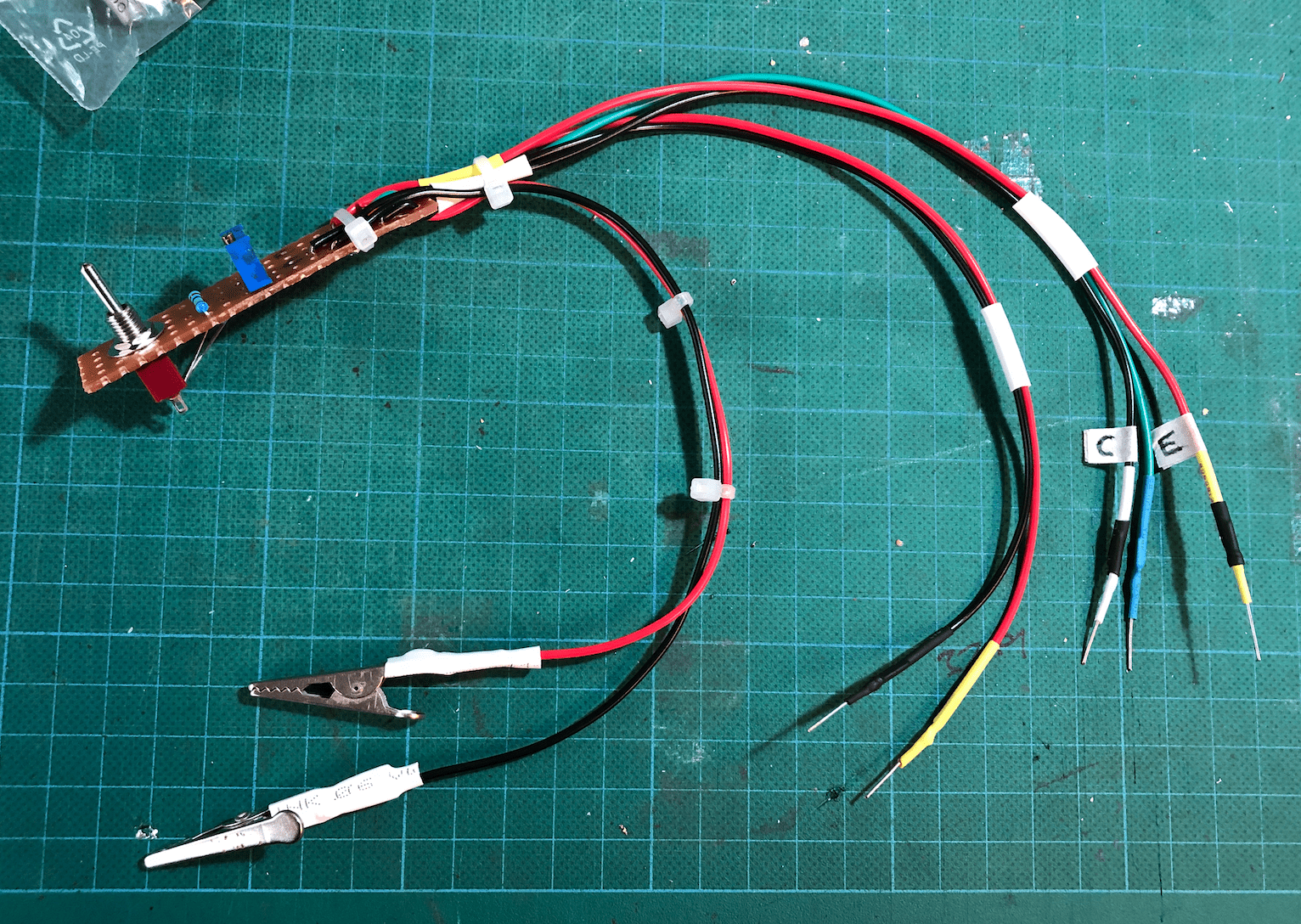
It’s not the best-looking thing I’ve ever made, but it feels solid, and it works as intended. I wish I had more colour options for the wires and shrinkwrap to make it easier to identify the leads, but it’s not the end of the world. I might even get around to mounting it in an enclosure one day with a small breadboard attached.
- This is specifically laid out for PNP germanium transistors; if you want to measure NPN, reverse the polarity of power and the multi-meter
- Components must be as close as possible to the values provided to provide the most accurate results (including voltage)